How to capture high-quality, undistorted images for industrial machine vision
Machine vision systems rely on digital image sensors mounted inside industrial cameras with specialised optical features to capture images.
These images are then analysed to make decisions based on their various characteristics. For example, in a fill-level inspection system at a brewery, every bottle passes through an inspection sensor that triggers a vision system to flash a light and take a picture of the bottle. The captured image is stored in memory and processed by vision software, which determines whether the bottle passes or fails and issues a pass-fail response based on its fill level. If a bottle is improperly filled, the system signals a diverter to reject it. Without sensors, it is impossible to capture and interpret visual information in machine vision systems. This article explains how to acquire high-quality images through image sensors for industrial machine vision applications.
Machine vision systems are capable of inspecting hundreds of parts per minute. They can perform tasks such as barcode scanning, locating, and surface defect identification. To achieve reliable results, vision system tools must include highly accurate image sensors. There are two main types of image sensors based on the capturing technique:
- Linear image sensors: These capture images one line at a time. They consist of a single row of pixels (photosensitive elements) that record light intensity sequentially as an object or scene moves past the sensor, or as the sensor itself moves.
- Area image sensors: These capture a two-dimensional area at once. They consist of a grid of pixels that record light intensity over the entire sensor area, creating a complete image in a single exposure.
Both linear and area image sensors can operate in various wavelength regions, including short wavelength infrared (SWIR), near infrared (NIR), visible (VIS), ultraviolet (UV), and X-ray. High-speed, high-sensitivity, and wide dynamic range image sensors can be used for different applications in industrial imaging, such as machine vision cameras, microscopy, and distance measurements.
Types of image sensing: Linear image sensors and area image sensors
In Linear Image Sensors, either the object or the sensor moves, allowing the capture of subsequent lines that are then stitched together to form a complete image. These sensors offer high resolution in one dimension, making them suitable for detailed inspections. They are commonly used in applications where the object or scene is moving, such as on conveyor belts in industrial environments.
An Area Image Sensors typically consists of an array of pixels arranged in rows and columns, capturing two-dimensional information instantly. These sensors are usually employed in security cameras to monitor areas in real-time.
Imaging with CMOS image sensors
CMOS image sensors are sensitive to both visible and non-visible light, such as ultraviolet and near-infrared, as well as visible light. They convert optical information into electrical signals and consist of the following components:
- Photosensitive area: Photodiodes detect the incident light and convert it into an electrical signal.
- Charge detection section: This section converts the signal charge into an analog signal, such as voltage or current.
- Readout section: This section reads the analog signal for each pixel.
The sensor chip includes a timing generator and bias generator required for the CMOS process. CMOS image sensors can be operated by inputting CLK, ST, and a single power supply. Figure 1 illustrates the block diagram of a CMOS image sensor, while Figure 2 shows the pixel arrangements for both area and linear types.

Figure 1: Block diagram of CMOS image sensor (Source)

Figure 2: Pixel arrangement of CMOS image sensors. (a) CMOS area image sensor, (b) CMOS linear image sensors. (Source)
Operating principle of CMOS image sensors
CMOS linear image sensors operate in two ways: rolling shutter and global shutter.
- Rolling shutter: Integration timing is shifted for each pixel (see Figure 3a). This means that each row of pixels is exposed at slightly different times. When imaging a fast-moving object, a rolling shutter will distort the image due to the time deviation in integration.
- Global shutter: Integration is done simultaneously for all pixels (see Figure 3b). This method eliminates image distortion when capturing fast-moving objects and detecting light pulses because all pixels capture the image at the same time.
Due to such characteristics, global shutters are best for fast-moving objects and detecting light pulses, such as in machine vision. In contrast, rolling shutters are suitable for detecting constant light.

Figure 3: (a) Integration time in rolling shutter (Source)

Figure 3: (b) Global shutter (Source)

Figure 3: (c) Imaging of fast-moving objects (Source)

Figure 3: (d) Distortion in rolling shutter (Source)

Figure 3: (e) Undistorted image in global shutter (Source)
Input output characteristics
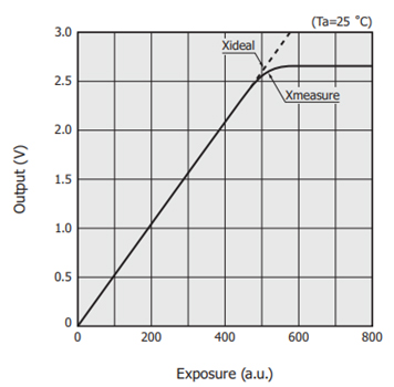
The input/output characteristics express the relation between the incident light level and the output. Incident light level is expressed by exposure (illuminance x integration time).

Figure 4: Triboelectric charging (Source)
A typical example of input/output characteristics for an image sensor is shown in Figure 4. As exposure increases, output increases linearly until it reaches saturation. The exposure at which output reaches saturation is called the saturation exposure. The saturation output is an index that determines the maximum level of the dynamic range.
Avoiding the dark output from image sensors: Dark output is usually caused by photodiodes. It occurs when carriers in the photodiodes get excited by heat from the valance band to the conduction band. Dark output increases proportionally with integration time, so the integration time must be carefully managed to control dark output. Additionally, dark output changes exponentially with temperature due to more carriers being excited at higher temperatures. Thus, dark calibration is necessary to remove the dark current contribution to the pixels.
Estimating dark current: This is estimated from pixels isolated from the light under the metal layer.
Subtracting dark current: The average dark current value, measured at each frame, is subtracted from all active pixels. The isolated pixels are part of the dark lines, and the dark current is assumed to be the same on dark and active lines.
However, there might be a mismatch of dark current between dark lines and active lines at high temperatures above 90°C. In such cases, the dark current on dark lines is slightly higher than on active lines, which leads to too dark images.

Figure 5: Demonstration of the need for dark offset compensation above 100°C (Source)
To address this mismatch and the resulting information loss, a reference dark level value is stored in the sensor's non-volatile memory (NVM). This allows for the calculation of a corrective dark offset. The number of pixels (Nb) affected can be adjusted accordingly to correct the artefacts from visible light.
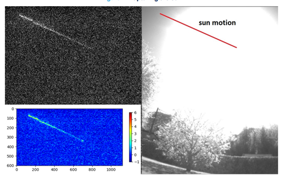
Correcting the artefacts from visible light: Image sensors are sensitive to extremely bright and sharp illumination in the visible spectrum, whether the sensor is powered or streaming. For example, the sun and other intense light sources might cause artefacts in the picture sensor.

Figure 6: Image generated over time by the sun, as captured by the sensor (Source)
The light trail in the upper left of the image is created by the sun as it travels across the sky, with only the sun’s center drawing the line (Figure 6). After being exposed to sunlight, the picture was captured at a high gain in the dark, using 10-bit codes for the light colors. Without light, this artefact rapidly fades, though some remanence can persist. The afterglow of the artefact is significantly influenced by the light source’s power density, the stress duration, and the optical stack. This artefact requires a high analog gain and a dim environment to be visible.
Indoor lighting and scattered reflected light won't produce noticeable artefacts in the photos. This effect does not apply to applications that use infrared illumination.
As a global distributor, we partnered with top suppliers to offer an extensive, wide range of image sensors
Conclusion
Achieving high-quality, undistorted images at high speeds in industrial machine vision requires advanced image sensors. Unlike rolling shutters, CMOS sensors, particularly with a global shutter, effectively capture fast-moving objects without distortion. To ensure optimal performance, manage dark output through calibration and use image sensors sensitive to a wide range of light, including non-visible spectra. Addressing artefacts from bright visible light is crucial to maintain image integrity, particularly in environments with extreme illumination. Proper sensor selection and calibration are essential for reliable, high-speed imaging in industrial applications like fill-level inspection in breweries.
Stay informed
Keep up to date on the latest information and exclusive offers!
Subscribe now
Thanks for subscribing
Well done! You are now part of an elite group who receive the latest info on products, technologies and applications straight to your inbox.
Related Articles
- Advanced ML for MEMS Sensors: Enhancing the Accuracy, Performance, and Power consumption
- How to design a MEMS Vibration Sensor for predictive maintenance
- Precision in Sight: How AI-powered visual inspection improves industrial quality control
- How to Capture High-Quality, Undistorted Images for Industrial Machine Vision
- Robotics and AI Integration: Transforming Industrial Automation
- The modern challenges of facial recognition
- Intelligent cameras for smart security and elevated surveillance
- Evolution of voice, speech, and sound recognition
- AI and IoT: The future of intelligent transportation systems
- Machine Vision Sensors: How Machines View the World
- Demystifying AI and ML with embedded devices
- How to implement convolutional neural network on STM32 and Arduino
- How to do image classification using ADI MAX78000
- The Benefits of Using Sensors and AI in HVAC Systems
- Deep learning and neural networks
- Latest Trends in Artificial Intelligence
- Hello world for Machine Learning
- How to implement AR in process control application


