MEMS sensors: A deep dive into emerging trends and cutting-edge innovations
Sensing technology has evolved from rudimentary (like thermal sensors and strain gauges) to cutting-edge analytical systems (motion sensing accelerators, gyroscopes, etc.).
This technology has seamlessly integrated into various facets of daily life, facilitated by wireless technology and MEMS sensors. These sensors, sufficiently compact to fit into wearable devices, allow individuals to monitor their health. Furthermore, sensor fusion coupled with Artificial Intelligence (AI) and Machine Learning (ML) algorithms ensures the creation of safe industrial environments. This integration extends beyond industrial settings into home automation and smart farming, revolutionizing how we interact with our surroundings. Furthermore, MEMS sensors are poised to revolutionise environmental monitoring, potentially detecting and analysing air and water quality in real time. This article takes a journey through sensor technology with advances in various sensing parameters and discusses potential and trends in sensor applications.
Future of sensor technology
In the future, sensors will transition into ‘smart’ sensors, marked by several technological advancements. These advancements include miniaturization, standardization, safety, speed, accuracy, wireless connectivity, and self-learning capabilities. Consumer electronics, including smartphones, tablets, and video game systems, have MEMS sensors. In addition, the technology is also integrated into various other applications, including wearable electronics for the health and fitness markets. The design of MEMS sensors continuously advances with ultra-low-power devices having a smaller footprint, which helps integrate the technology with system-in-package (SiP) devices or smart miniaturized modules. This will enable the development of smart products by augmenting the computational ability of microelectronics with the perception and control capabilities of microsensors and microactuators.
How advanced MEMS technology solves complex sensing challenges
MEMS technology consists of highly precise miniature mechanical and electromechanical elements. Micro-fabrication technology allows the creation of devices with dimensions ranging from one micron to several millimeters. This micromachined version of sensors outperforms the ones using the most precise macroscale level machining techniques. Their production method uses the same batch fabrication techniques used in the integrated circuit industry, which can translate into low per-device production costs and other benefits. At the same time, they keep battery demand low for longer runtimes. MEMS sensors have a stiffer load-bearing structure and smaller strain levels, producing ten times the output than conventional sensors. It delivers precise, reliable sensors that combat fatigue and drift and provides long-term stability at a low cost. Some of the distinct features of MEMS sensors have made them exceptional compared to traditional sensors. They are:
Size: One remarkable feature of MEMS sensors is their impressive functionality, despite being extremely small, measured in millimeters (µm). The microstructures micromachined on silicon wafers are shown in Figure 1. This size also makes it possible to optimize the amount of die produced on each wafer used for fabrication. The batch of sensors produced is in bulk, making it a lower cost die for the customer without losing superior performance. This has made continuous health monitoring possible with wearable sensors. The miniature size also helps it to be embedded in mobile phones, portable devices, etc.
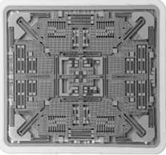
Figure 1: Mechanical structures integrated and micromachined on silicon wafers for sensing(Source)
Accuracy: The accuracy of the sensor refers to the maximum variation between the actual and displayed values at the output. It can be expressed as a percentage of full scale or in absolute terms. MEMS sensor modules typically include pre-calibrated data stored in the module’s non-volatile memory (NVM). The sensor uses the calibration coefficients in the NVM to produce stable measurements. It can be operated to a maximum deviation of ±1% over the module’s lifetime. An example of the RRH46410 MEMS Gas Sensor’s accuracy in measuring indoor air quality for CO2 is shown in Figure 2.
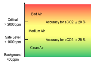
Figure 2: Concentration dependent accuracy for eCO2(Source)
Nonlinearity: Nonlinearity measures the deviation from a perfectly constant sensitivity, specified as a percentage concerning either full-scale range (%FSR) or ± full scale (%FS). Typically, FSR = FS+FS. The nonlinearity of MEMS sensors is sufficiently low to make sensor application possible in autonomous vehicles, robotic surgery, etc. The slight deviation between the actual value and the sensing value of the MEMS sensor is shown in Figure.3
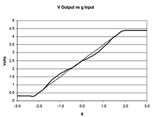
Figure 3: Output of the MEMS sensor, with a gray line indicating the measurement deviation or nonlinearity(Source)
Precision: If bandwidth and resolution are considered, the MEMS accelerometer, ADXL362 from ADI, as shown in Figure 4, can be an illustrative example. Unlike under-sampling methods that may lead to signal aliasing, this accelerometer samples the total bandwidth of the sensor at all data rates while maintaining low noise levels. This enables the most minor signals to be measured. For applications where a noise level lower than the standard 550 µg/√Hz of the ADXL362 is desired, either of two lower noise modes (down to 175 µg/√Hz) can be selected at a minimal increase in supply current. This enhances the precision of output reading.

Figure 4: FADXL362BCCZ-RL7 (MEMS accelerometer)(Source)
Reliability: MEMS technology has enabled the development of mechanically robust, high-performance sensor designs. This, coupled with a hermetically sealed, silicon capping process for packaging, helps to deliver genuinely reliable long-life MEMS switches.
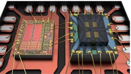
Figure 5: Drive IC (left), MEMS switch die (right) mounted on and wire bonded to a metal lead frame(Source)
Figure 5 shows a single-die MEMS switch and a driver IC mounted in the frame. To make the MEMS component as easy to use as possible and further guarantee performance, a companion driver integrated circuit (IC) has been specifically developed to generate high DC voltages and co-packaged with the MEMS switch in a quad flat no-lead package (QFN) form factor.
Sensor Signal Conditioning circuits by Farnell: ZSC31010KITV2P1, SSCCOMMBOARDV4P1C, LMH6401EVM, PGA450Q1EVM, ZSC31050KITV3P1, STM32F427ZGT6
Condition monitoring and predictive maintenance using MEMS sensors
Infrastructures need maintenance to ensure that they function correctly. An unscheduled downtime due to parts wearing out can mean lost productivity. You must replace components instantly to avoid inconvenience or expensive overtime rates, and continually monitor a device or system to provide an early warning for any unfortunate occurrence. In this context, vibration sensors can be used for condition monitoring. It is possible to monitor the machine's health to make an informed decision on the timing of the replacement based on a detailed understanding of its actual fault status.
Vibration sensing using a 3D magnetic MEMS sensor
Vibration monitoring is often used for condition monitoring as it provides an early warning that a mechanical device is not running smoothly. A part that starts to wear moves asymmetrically and with a detectable vibration. More details can be determined as to the precise cause, such as load imbalance, misalignment, or ball bearing wear, with appropriate analysis of the amplitude and frequency of the vibrations. A Hall-based, 3D magnetic sensor makes such monitoring possible. This sensor detects changing magnetic fields; thus, no physical connection is needed. For example, Figure 6 shows a magnet attached to a shaft while the sensor is positioned on the housing, provided it does not block magnetic fields.
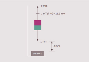
Figure 6: A 3D magnetic sensor is used to detect linear movement. In this illustration, a cylindrical bar magnet is shown as a red and blue block that moves closer or further away from the sensor in a ‘heads on’ configuration (Source)
b. Barometric MEMS pressure sensor for air-flow measurement
The sensor can be placed inside the pipe to monitor pressure and gas flow rates. There is no need to cut access into the pipe to sample the pressure inside. Air flowing over the curved wing surface causes a drop in air pressure that lifts the wing, as shown in Figure 7. Pressure sensors are designed with a membrane to protect the sensor structure from dirt, humidity, and liquids.
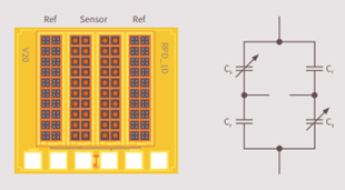
Figure 7: The cell structure of the capacitive MEMS pressure sensor enables differential measurements with very low-temperature drift(Source)
The capacitive barometric pressure sensor consists of four arrays of sensing and reference cells. The flexible membrane in the sensing cells reacts to pressure changes and provides the air pressure measurement. MEMS sensors need minimal vibration or pressure input compared to traditional sensors with large structures. They are thus suitable for predictive maintenance applications.
Sensor Fusion
Sensor fusion is a process by which data from several different sensors are 'fused' to compute insights beyond what any individual sensor could provide alone.
Using Sensor Fusion to Improve the Performance of Tilt Sensors
A mass is added to the sensor silicon die in a MEMS-based tilt sensor. The force of gravity deflects the die in the horizontal position, producing an electrical output. As the die is rotated to the vertical position, the force on the die goes to zero, as does the electrical output. The output is digital and calibrated in terms of tilt angle in degrees. MEMS-based tilt sensors have addressed many issues associated with liquid-based technologies.
The function and accuracy of a tilt sensor is affected by many factors. Some of these factors are gravity, temperature, calibration of the tilt sensor, linearity, and cross-axis sensitivity. A few critical specifications of a tilt sensor include the number of axes, resolution, measuring range, noise tolerance, vibration, and shocks.

Figure 8: Illustration of a modern tilt sensor based on MEMS technology(Source)
MEMS-based tilt sensors use gravity as the acting force on the sensing element. A typical approach for a MEMS tilt sensor would include a 3-axis accelerometer where gravity acts on each axis depending on the tilt angle. The signals are temperature-compensated and linearized, and the actual tilt angle is calculated from the 3D acceleration data, as shown in Figure 8. However, any additional acceleration, e.g., vehicle speed changes, leads to distortion of the calculated tilt. The combination of an accelerometer and a gyroscope is thus a preferred approach. The strength of the other compensates for the weakness of one sensor. A gyro sensor measures the rotation rate or angular velocity around a particular axis.
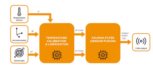
Figure 9: Gryo-stabilized tilt sensor fuses acceleration, rotation, and temperature data to provide accurate tilt information in dynamic applications(Source)
The gyro-stabilized tilt sensor combines a 3-axis accelerometer, a gyroscope, a temperature sensor, and a sophisticated MCU in one compact package, as shown in Figure 9. Algorithms take data from different sensors, compensate for temperature effects, and fuse them to yield a stabilized but fast-tracking tilt output signal.
Conclusion
The key strength of MEMS switches is their ability to offer precision and accuracy despite their compact size. They deliver wideband RF performance and superior reliability compared to relays in a tiny surface-mountable form factor. The mechanical structure of MEMS assures high reliability and excellent performance, surpassing conventional sensors. By incorporating AI technology at the edge, modern sensors can collect, process, and send meaningful data in real time. AI or ML-based enhanced sensor fusion can be implemented at various system levels, including the data, fusion level, and decision levels.
Farnell has partnered with suppliers catering to various industrial and embedded sensor accessories such as IC Sensors,MEMS Accelerometers,MEMS Modules,MEMS Gyroscopes,Pressure Sensors, and Sensing Development Kits.


