Mastering antenna design: optimize wireless connectivity
Introduction
Antennas are an essential component of every wireless communication system. The efficiency and effectiveness of antennas is critical to the success of any wireless communication system. As the need for seamless wireless communication expands, it becomes essential to understand the complexities of antenna design and the elements that contribute to optimal performance. Wireless connectivity has become an indispensable aspect of our daily lives, linking gadgets and allowing communication across long distances. Wireless communication, on the other hand, has various drawbacks, including limited range, prolonged data transfer, and signal interference. A good antenna is an effective wireless communication option. An antenna's design impacts how successfully it can broadcast and receive signals. Engineers can design better-working antennas by considering factors such as radiation pattern, impedance matching, frequency range, and polarisation. These factors influence the range of antennas, increase the speed of data transfer, and make signals stronger.
This article will dive into how antenna design concerns affect wireless connectivity. We will go through the aspects that influence antenna design, operation, and type. We will also go through antenna selection and design considerations.
Fundamentals of antenna
An antenna consists of a conductor that is exposed in space. An antenna is formed when the length of the conductor is a specific ratio or multiple of the wavelength of the signal. As the electrical energy provided to an antenna is radiated into free space, this phenomenon is known as "resonance".
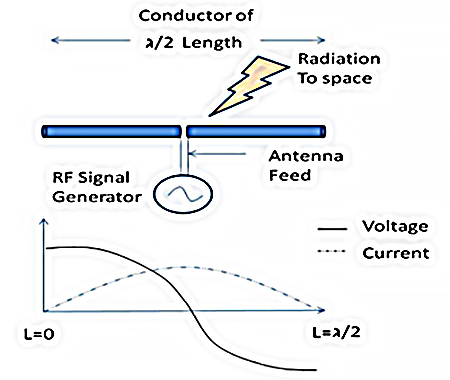
Figure 1: Dipole antenna basic
In figure 1, the wavelength of the electric signal (λ) is twice the size of the metal part. The antenna receives the signal from the signal generator through a transmission line called the “antenna feed”. The figure shows the current and voltage form along the metal part when the wavelength is twice the length. This type of antenna is termed a dipole antenna. However, However, on printed circuit boards, most antennas work equally well by using a metal a quarter of the wavelength (λ/4) and arranged in a specific way.
Types of antennas
Any conductor of length λ/4 exposed in free space over a ground plane with an appropriate feed can be an effective antenna, as explained in the preceding section. The antenna can be as long as a car's FM antenna or as small as a trace on a beacon, depending upon the wavelength. For use with 2.4-GHz applications. In this section, we will look at some of the most common types of antennas:
1. Monopole antenna
The Monopole antenna is an unbalanced antenna with a single-quarter wavelength element. It is made up of a single conductor suspended above a conducting surface, usually the ground plane. Vertically polarised monopole antennas feature a half-omnidirectional radiating pattern. They are frequently employed in mobile devices, cellular base stations, and other applications where space is limited.
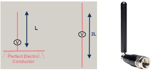
Figure 2: Monopole antenna
2. Dipole antenna
The Dipole antenna consists of two physical elements, each of which is a quarter wavelength. The directivity is the same as the Monopole, but the use of two physical quarter wavelength elements instead of one, with support from a ground plane reflection results in a potential gain of up to 3dB over the Monopole in some configurations. They are extensively utilised in mobile devices, cellular base stations, and other applications where space is constrained.
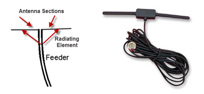
Figure 3: Dipole antenna
3. Loop antenna
Due to its simplicity and ease of construction, loop antennas resemble both dipole and monopole antennas in terms of their features. Loop antennas come in a variety of shapes, including circular, elliptical, and rectangular, etc. The configuration of the loop antenna has little bearing on its basic properties. They have a frequency of about 3 GHz and are commonly employed in communication networks. In microwave bands, these antennas can also be utilised as electromagnetic field probes.
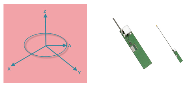
Figure 4: Loop antenna
4. PCB antenna
This is a trace drawn on the PCB. Depending upon the antenna type and space limits, this can be a straight trace, an inverted F-type trace, a meandering trace, a circular trace, or a wiggled curve. In a PCB antenna, the antenna becomes a two-dimensional (2D) structure in the same plane as the PCB; see Figure 5. There are guidelines that must be observed whilst the 3D antenna exposed in free space is transported to the PCB plane as a 2D PCB trace. A PCB antenna requires greater PCB space, has a less efficiency than a wire antenna, but is less expensive. It is simple to manufacture and provides an adequate wireless range for a BLE application.
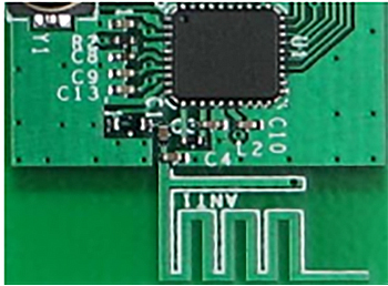
Figure 5: PCB antenna
5. Chip antenna
This is an antenna in the shape of a tiny form-factor IC with a conductor packed within. When there isn't enough room to print a PCB antenna or support a 3D wire antenna, this is useful. Figure 6 depicts a Bluetooth module with a chip antenna. The size of the antenna and module in relation to a one-cent coin is shown below.
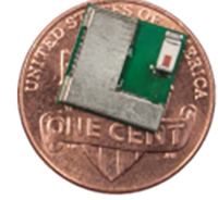
Figure 6: BLE module (10 mm × 10 mm) with chip antenna
Choosing an antenna and antenna design considerations
There are various key characteristics to consider when developing an antenna for wireless connectivity. These characteristics contribute to the antenna's performance and efficiency in transmitting and receiving signals. Here are some key antenna parameters to consider:
- Gain: In contrast to an isotropic antenna, which radiates uniformly in all directions, gain indicates the radiation in the direction of interest. This is expressed in decibels (dB)—how intense the radiation field is in compared to an ideal isotropic antenna.
- Bandwidth: The frequency response of an antenna is indicated by its bandwidth. It denotes how well the antenna is matched to the 50Ω transmission line across the whole spectrum of interest, which for BLE applications is between 2.40 GHz and 2.48 GHz.

Figure 7: Bandwidth
- Return loss: An antenna's return loss indicates how well it is matched to the 50Ω transmission line (TL), illustrated as a signal feed in Figure 8. The normal TL characteristic impedance is 50Ω; however, it might be a different number. Return loss (Equation 1) specifies how much of the incident power is reflected by the antenna owing to a mismatch. When precisely aligned, an ideal antenna will radiate the entire energy without any reflection. The antenna is perfectly matched to the TL if the return loss is infinite, as shown in Figure 7. S11 is the inverse of return loss in dB. In most circumstances, a return loss of 10 dB (equal to S11 -10 dB) is deemed enough. The return loss (dB) is proportional to the power reflected by the antenna (percent). A return loss of 10 dB indicates that 90% of the incident power is utilised by the antenna for radiation.
- Radiation efficiency: A portion of the non-reflected power (see Figure 8) is dissipated in the antenna as heat or thermal loss. The dielectric loss in the FR4 substrate and the conductor loss in the copper trace cause thermal loss. This data is referred to as radiation efficiency. A radiation efficiency of 100% means that all non-reflected power is radiated to free space. The heat loss on a small-form-factor PCB is low.
- Radiation pattern: The radiation pattern reveals the directional feature of radiation, that is, which directions have more, and which have less radiation. This information aids in appropriately orienting the antenna in an application. In the plane perpendicular to the antenna axis, an isotropic dipole antenna radiates equally in all directions. Most antennas, however, vary from this optimal behavior. Figure 9 depicts the radiation pattern of a PCB antenna as an example. Each data point shows RF field intensity as measured by the receiver's received signal strength indicator (RSSI). Because the antenna is not isotropic, the contours are not quite round, as predicted.
- Size and form factor: The physical size and shape of the antenna are crucial factors to consider, particularly in space-constrained applications. To accomplish the necessary size and shape while keeping high performance, miniaturisation techniques and alternative antenna topologies can be used.
- Interference and noise: When designing an antenna, consider variables such as interference and noise sources that may impair signal quality. Filtering and shielding are two antenna design strategies that can assist reduce the impact of external interference.

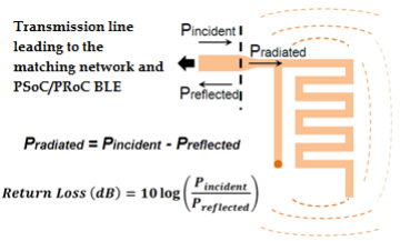
Figure 8: Return loss
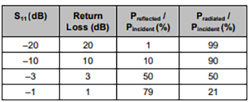
Table 1: Return loss and power reflected from antenna
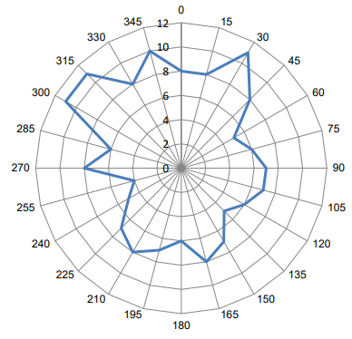
Figure 9: Radiation pattern
Conclusion
As more products become wirelessly connected, antenna design recommendations will become increasingly crucial for PCB and industrial designs. To prevent costly delays and changes in architecture that may have a substantial influence on time-to-market and development costs, antenna design must be thoroughly considered early in the development cycle.
Farnell has partnered with many different suppliers catering to a wide range of antenna portfolios for wireless connectivity, such as antennas,.antennas - RFID, RF antennas,WiFi antenna,NFC antenna,antennas - dual band chip and antennas - single band chip


