How to interface temperature and pressure sensor with LabVIEW
LabVIEW is a graphical programming language that uses icons instead of text-based instructions to create applications. Temperature and pressure sensors can be interfaced with LabVIEW to monitor and control the temperature and pressure specific to any application, dictated by application needs. The way to interface temperature and pressure sensor with LabVIEW depends upon the type of sensor.
A sensor that provides digital (serial) output can be directly interfaced via a serial port. Analogue sensors require a data acquisition module (DAQ) which receives an analogue input signal and provides the digitised data to LabVIEW. Various DAQs are available depending upon the input and output channels from National Instruments (NI). A signal conditioning circuit can make a sensor output compatible with the DAQ input range and remove noise, but this is optional if we use a DAQ with an in-built signal conditioner and sensor compatible with the input range of DAQ.

Figure 1: General block diagram to interface temperature and pressure sensor with LabVIEW
Figure 1 shows a general block diagram to interface an analogue temperature sensor and pressure sensor with LabVIEW. For example, we will connect an analogue temperature sensor LM31 and pressure transducer (P51-1000-S-B-I36-4.5V-000000) using USB-6008, a low-cost, multifunction DAQ device from NI.
LabVIEW includes several wizards to configure DAQ devices and build applications quickly. It has a set of tools to build a user interface, known as the front panel, which has graphical representations of functions to control the front panel objects. The block diagram contains the methods (code). Users interact with the Front Panel when the program is running and control the program, change inputs, and see data updated in real-time. Perform the following steps for hardware connection and writing of a program for interfacing.
Hardware connections
Make the hardware connection as shown in figure 2. Temperature sensor LM35 is powered through the DAQ +5Vdc supply, and its output is connected to the AI0 channel of DAQ. Similarly, the output of the pressure transducer is connected to the AI1 channel of DAQ. A separate +5Vdc can power the pressure transducer, keeping the ground terminal common to DAQ. Finally, the DAQ is connected to the LabVIEW system via a USB cable. When DAQ is connected with the system, it automatically installs the driver for DAQ.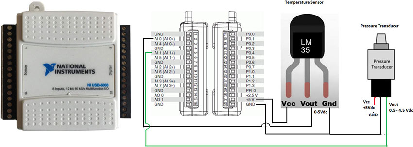
Figure 2: USB-6008 DAQ, terminals and hardware connection
LabVIEW program
Complete the following steps to write a LabVIEW program. Open the LabVIEW application.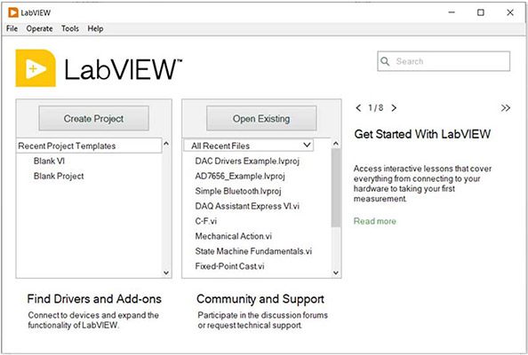
Figure 1: Opening LabVIEW window
Click on Blank VI, which opens two windows for Front Panel and Block Diagram.
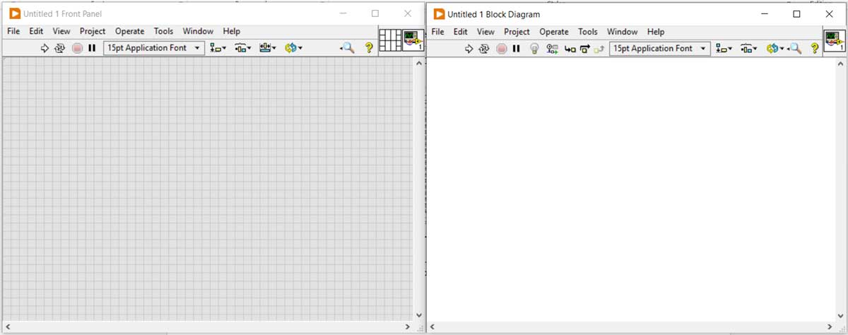
Figure 2: Front panel and block diagram
Right-click on Block Diagram window and go in Express->Input and click on DAQ Assist
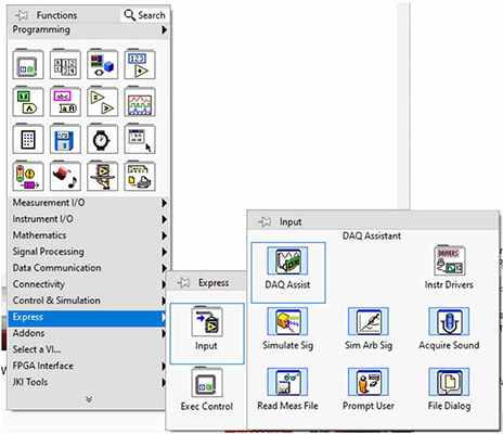
Figure 3: Selecting DAQ assist
DAQ assist will open a window to configure DAQ for the input signal. Navigate to Acquire Signal->Analog Input and select Voltage option. It will now show the connected DAQ device for all input and output channels. Select AI0 and AI1 as the input signals are connected to these channels in voltage form. Finally, click on the Finish button.
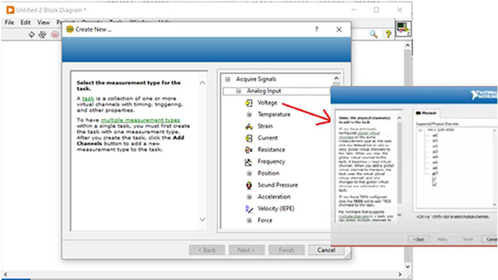
Figure 4: Selecting DAQ analog channels
After clicking on Finish Button, a configuration window will open as shown. Fill the maximum and minimum range (5 and 0, as per output range of temperature sensor) for the AI0 input channel, and set the terminal configuration to RSE. Acquisition Mode is set to one sample on demand. Apply the same procedure for the AI1 channel for pressure sensor output range (4.5 – 0.5Vdc) and click the OK button. Finally, LabVIEW will create a VI for DAQ.
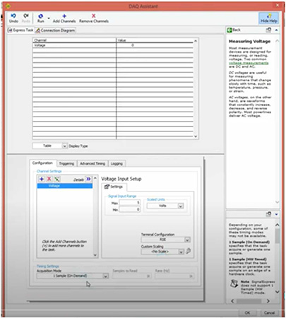
Figure 5: Configuring DAQ analog channels
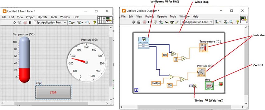
For continuous measurement in a specific duration, keep the DAQ Assist VI in While Loop and put a Wait (ms) timing VI. To calculate ambient temperature, multiply AI0 channel data to 100 (as temp. sensor outputs 10mV/°C) and add 25 offsets for room temperature. The full output range (0.5Vdc to 4.5Vdc) of the pressure sensor from the AI1 channel is scaled from 14.7 to 1000 PSI using some mathematical algorithm. Finally, the output in temperature °C and pressure in PSI are shown using a thermometer and gauge indicator on the front panel, as shown (fig 6).
