How to implement smart metering in EV charging
Introduction
Smart metering is a cutting-edge technology that allows for real-time monitoring, measurement, and management of electricity consumption. It plays an essential role in evolving conventional charging systems into intelligent and efficient networks in the context of Electric Vehicle (EV) charging. With the increasing acceptance of electric vehicles, there is a greater need for a reliable and scalable charging infrastructure. Smart Metering in EV charging is vital for optimising energy usage, ensuring grid stability, and providing EV owners with a seamless charging experience. This article explores the integration of smart metering in EV charging, which enables certain tracking of energy use, dynamic pricing models, and efficient load management. Smart metering allows the optimal use of renewable energy sources and reduces the overall environmental impact of EV charging infrastructure.
The structure and characteristics of smart meter
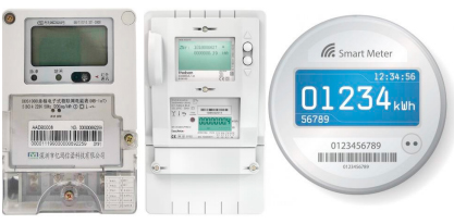
A smart meter works based on a microprocessor application and network communication technology. In Fig. 1, for example, there are two types of smart meter products. It is assembled from standard electronic watt-hour meters, LED displays, metering components, communication ports, CPU, memory, IO, and other components. It allows for local calculations and remote real-time data interaction with cloud servers. It offers automatic metering, data processing, two-way communication, and function expansion capabilities. It can support two-way metering, remote and local communication, multiple electricity price billing, remote power outages, power quality monitoring, and user interaction.

Figure 1: Types of smart meter components
Smart meters have advanced metering infrastructure (AMI) and automatic meter reading system (AMR), delivering detailed power consumption information to users. Such information helps users to manage their power consumption better and thus save money on electricity and reduce greenhouse gas emissions. Simultaneously, electricity retailers can formulate flexible time-of-use electricity prices to reform the electricity market price system; power distribution companies can detect faults more quickly and respond in time to strengthen power network control and management.
Smart charging
Smart charging (V1G) and vehicle-to-grid (V2G) are viable technologies for intelligently connecting electric vehicles with the electric grid. V1G enables you to manage the power flow from the grid to the car by regulating the charge's time (start and end) and amperes. V2G goes beyond V1G by allowing the power flow to be reversed, making the electric vehicle both a programmable load and a programmable generator; thus, V2G outperforms V1G since the benefits obtained by implementing V2G are theoretically larger than those obtained by implementing V1G.
In general, an electric car can be charged quickly at a charging station or slowly at home, as shown in the following figure: in the first case, the batteries are linked to the charging station's off-board charger, while in the second, they are attached to the onboard charger. Off-board and onboard chargers, in general, are made up of a cascade of two electronic power converters, one AC/DC and one DC/DC, with high power density and efficiency. The unidirectional converters are relatively inexpensive and structurally simple in the V1G situation but more expensive and structurally complex in the V2G scenario. Furthermore, the firmware on microprocessors, communication protocols, quantity of sensors, and converter certifications differ significantly from V1G to V2G. The off-board charger, for example, typically converts the phase-to-phase AC voltage of grid cables to a DC voltage, and the vehicle batteries are directly DC coupled to this charger; thus, a V1G off-board charger may consist of a conventional diode rectifier in cascade with a DC/DC buck/boost converter for power factor correction (PFC).

Figure 2: Off-board and onboard chargers for an electrical vehicle
The corresponding V2G charger, on the other hand, may consist of a three-phase bidirectional AC/DC converter mounted with six insulated-gate bipolar transistors; if the battery voltage is lower than the voltage at the rectifier's terminals, a single or interleaved bidirectional buck/boost DC/DC converter is added to the cascade. Similar concerns apply to the onboard charger: it typically transforms the residential cable's phase-to-neutral AC voltage to a DC voltage. V1G contains a diode rectifier and a DC/DC buck converter with power factor adjustment in a cascade. A full-bridge AC/DC boost converter, a half-bridge bidirectional DC/DC converter, or a bridgeless boost-type AC/AC converter in cascade to an interleaved DC/DC buck-type converter are available in V2G.
Application of smart meter in the management of electric vehicle charging facilities
Electric meters currently provide a rudimentary measurement role in administering electric vehicle charging facilities. It can play the following roles in helping electric vehicle charging stations by expanding and optimising smart meters.
- Remote control:A smart meter contains relays, valves, and other action mechanisms that may receive remote instructions for switching operations provided by the electricity grid firms' management center. As a result, smart meters can perform real-time remote control.
- Real-time power measurement:Smart meters can measure the charging process in real-time. Electricity bill settlement, equipment status monitoring, and grid line loss analysis may all be accomplished on time thanks to real-time charging data collecting and automatic analysis. Power grid businesses can use this data to understand electric vehicle usage habits and power consumption and provide scientific and trustworthy information for increasing power supply quality, optimising charging decisions, and demand-side management.
- Power quality monitoring:The smart meter can detect power quality and alert the charging station before it fails by connecting with a power quality monitoring device. When harmonics or other difficulties caused by charging facility failure are exceeded, the charging process can be remotely terminated to avoid impacting other adjacent power users.
- Communication and network functions:Because some charging stations are underground or in isolated regions, the network communication function will be compromised. When the signal is bad, smart meters can use power lines to convey information via power line communication and even serve as wireless hotspots to realise intelligent network connection functions of electric vehicles and charging heaps.
- Demand response:With the owner's permission, a smart meter can receive remote instructions to alter the charging period of an electric car based on the grid load level and power price. Charging electric vehicles during low load periods or when electricity rates are low can help to lessen the peak-to-valley disparity in grid load and increase power grid operation efficiency. Smart meters offer two-way metering features, and electric car owners can earn cash by returning power to the grid during peak or emergency conditions.
How smart meters enable smart EV charging
As shown in Figure 3, the aggregator permanently communicates with all smart meters; therefore, it is aware of power flows at users' meters; based on this information, the aggregator manages the smart charging service, establishing which vehicles can be recharged. The smart meter measures the meter's power flow, but it also enables the smart charging service as it receives and implements the decisions of the aggregator; in this sense, the smart meter communicates to electric vehicle supply equipment (EVSE) so that batteries' charging begins.
As shown in the following Figure 3, the aggregator connects with all smart meters continuously, so it is aware of power flows at users' meters; based on this information, the aggregator runs the smart charging service, determining which vehicles can be refilled. The smart meter not only detects the meter's power flow but also enables the smart charging service by receiving and implementing the aggregator's decisions; in this sense, the smart meter communicates with electric vehicle supply equipment (EVSE) so that battery charging can commence.

Figure 3: The aggregator, the smart meter, and the EV Charging equipment

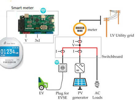
Figure 4: Connection of smart meter at a user's application
Figure 4 illustrates the smart meter installed in the home switchboard, and it calculates the power flow, measuring the voltage and the current at the switchboard input. In addition, the smart meter also measures the current of two main distribution lines: the line that supplies the EVSE and the line that connects the photovoltaic system to the grid.
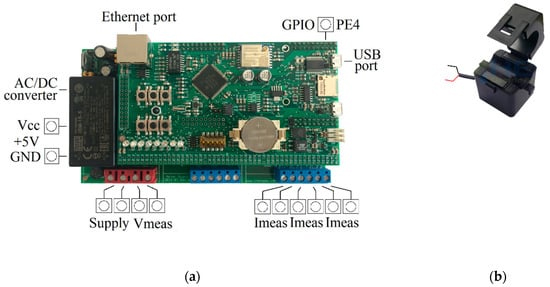
The smart meter, as shown in the figure below, is composed of two printed circuits, the first mainly devoted to signal processing, whereas the second is to power conditioning. The upper printed circuit processes the signals that correspond to the measured voltages and currents, calculates temporal averages, connects to the internet, and processes the rules for controlling the output ports, as will be described later. The lower printed circuit supplies power to all circuits and to some external auxiliary devices; it also transduces voltages and current measurements into signals, ensuring protection, isolation, and filtering.
Figure 4 shows a smart meter fitted in a house switchboard that calculates power flow by detecting voltage and current at the switchboard input. Furthermore, the smart meter measures the current of two primary distribution lines: the one that supplies the EVSE and the one that connects the photovoltaic system to the grid.
The image below indicates that the smart meter comprises two printed circuit boards. The first is primarily concerned with signal processing, whereas the second is concerned with power conditioning. As explained below, the upper printed circuit processes the signals corresponding to the observed voltages and currents, calculates temporal averages, connects to the internet, and processes the rules for controlling the output ports. The lower printed circuit gives power to all circuits and some external auxiliary devices and converts voltage and current measurements into signals for protection, isolation, and filtering.

Figure 5: (a) The smart meter, and (b) the open-core toroidal current transformer
A pair of terminals in the bottom left corner accept the 230 Vac-50 Hz grid voltage supply; an AC/DC converter straightens this grid voltage and provides a stable 5 Vdc voltage to power the smart meter's components and auxiliaries up to 15 W. For phase-neutral voltage detection, the second pair of terminals connects directly to the bus. Three pairs of terminals in the bottom right corner receive the output of three open-core toroidal current transformers for line current measurements, as shown in Figure 5b.
In terms of voltage/current measurement and power calculations, the smart meter has been developed for high-performance, high-frequency, and precise measurements, as well as a streamlined Internet connection to a cloud database. The only software present in this smart meter is the firmware stored in the microcontroller. The end user is not currently permitted to edit the firmware.
The smart meter takes 100 samples of the voltage and three currents every 20 milliseconds; the default frequency of 5 kHz can be increased if necessary. Every 20ms, three active powers are obtained, and temporal averages are calculated every 5s. The average values are recorded locally on a memory card, are cyclically rewritten, and are then transferred to a cloud database. The smart meter is outfitted with an ESP8266 chip to connect to the local Wi-Fi.
Stay informed
Keep up to date on the latest information and exclusive offers!
Subscribe now
Thanks for subscribing
Well done! You are now part of an elite group who receive the latest info on products, technologies and applications straight to your inbox.
Related Article
- Charging protocols and safety standards for EV Charging Infrastructures
- The Future of EV Infrastructure: Navigating trends, opportunities, and benefits
- A Developer's Guide for designing the EV Charging using the right tool
- Revolutionizing Electric Vehicles - Innovations in Motor Control Systems
- How to implement Smart Metering in EV charging
- How to design an efficient power conversion circuit for EV Chargers
- Transforming Mobility: The Architecture and Solutions of V2X Communication in Electric Vehicles
- The effects of electric vehicle charging stations to the power grid
- Cyber security of public charging stations
- Powering Up with Safety and Ease: The Art of EV Charger Design
- EV Charging Standards: Ensuring Compatibility and Safety in the Charging Process
- EV charging and renewable energy for sustainable transportation
- EV Charging and Battery Management System
- Wireless Power Transfer: A Convenient and Efficient Solution for EV Charging
- Design Considerations for High-Efficiency EV Chargers
- The benefits and challenges of electric vehicles
- Communication network for electric vehicle charging
- How to boost Level-3 EV charging with the right connectivity
- How SPI isolated communication helps BMS in EVs


