How to design a bidirectional Buck-Boost converter for modern EVs
As electrical systems in modern vehicles proliferate, the traditional 12 V electrical system of EVs (Electric Vehicles)/HEVs (Hybrid Electric Vehicles) is creaking under strain.
The relatively low voltage in a 12V system results in high currents that require substantial cabling, which is expensive, heavy, and difficult to route through the small spaces in modern EVs and impacts the efficiency of the vehicle. To address this, automakers have gradually introduced 48V systems that offer higher power whilst decreasing the weight and cost of wiring looms.
However, it is impractical to switch to a single 48 V system in the short term because of the volume of legacy 12 V products used in vehicles. The solution is to run 12 V and 48 V systems together, each with its own battery. Managing the power and charging of these different voltage systems can be complex if separate DC-to-DC converters are used for each. The introduction of bidirectional DC-to-DC converters—can act as a bridge between the 12 and 48 V systems—simplifies design, lowers cost, and encourages adoption in lower-priced cars.
The design:
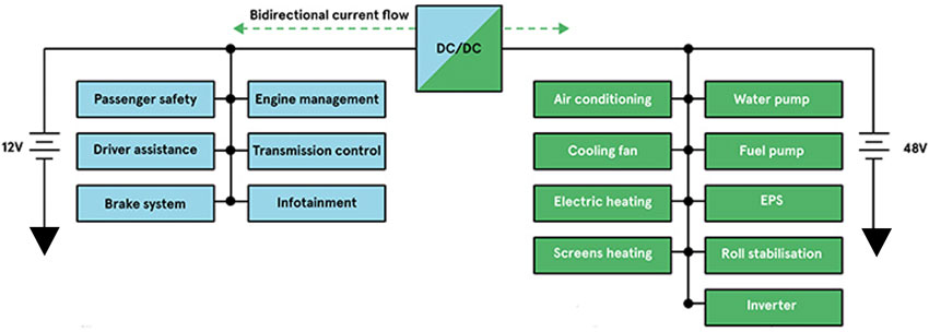
In a typical electric vehicle architecture, lower power applications can be connected on the 12V side, whilst the higher power applications (generally those requiring motors and heating elements) to the 48V. A bi-directional DC-DC converter is at the heart of these mixed voltage systems and bridges the two voltages. This important sub-system is both a step-down (‘buck’) and step-up (‘boost’) converter that allows either battery to be charged from the other (Figure 1).
The bi-directional approach allows the same external components (including passive devices such as inductors and capacitors) to be used for both the step-up and step-down conversions. As a result, size and weight are reduced, which improves the efficiency/range of the vehicle and lowers the manufacturing cost. The bi-directional DC-DC converter can also combine energy from both systems to provide as much power as possible when the current draw is at its greatest – for example when starting the vehicle.

Figure 1: Mixed 48V / 12V systems are generally segmented based on power requirements
A bidirectional DC-DC converter is grouped into two types based upon the galvanic isolation between input and output: Non-Isolated and Isolated Bidirectional DC-DC Converters. There is little need for galvanic isolation in automotive systems, as all voltages are separated extra-low voltage (SELV), this was part of the reason that 48V was chosen. So bi-directional DC-DC tends to be non-isolated to avoid the weight and cost of a transformer. Therefore, a non-isolated multi-device interleaved bi-directional DC-DC converter (MDIBC) is a common solution.
The 12V power is derived from a sealed lead acid battery, whilst the 48V source can be either a battery or a supercapacitor (SC) or, quite often, a combination of both, which gives the ability to deliver peaks of current when needed.

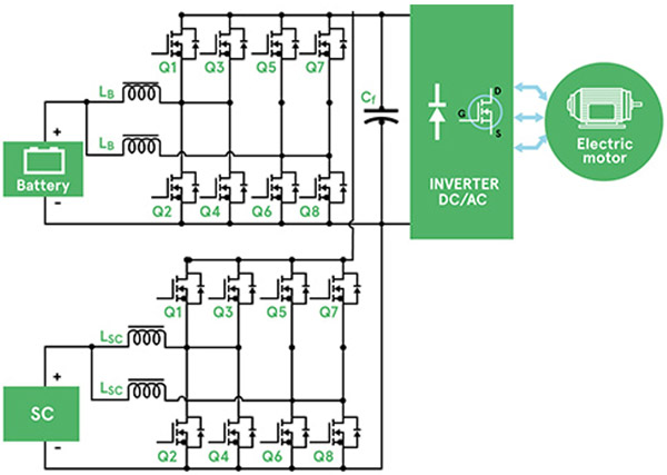
Figure 2: Schematic of Multi-Device Interleaved Bi-Directional DC-DC Converter (MDIBC)
The multi-phase approach of the MDIBC shown in Figure 2, which relies upon the gate drive signals to be interleaved, reduces the input ripple. In fact, acceptable input and output ripple levels can be achieved without increasing the value (and therefore, size and cost) of the passive components. The trend towards using wide bandgap (WBG) semiconductors is allowing operating frequencies to increase, which reduces the size of the passive components.
Unlike many conventional topologies, the MDIBC has commonality with the control circuit, thermal management, and the DC link capacitor, all of which add to the overall reliability. The ability to allow power to flow bi-directionally means that it can accommodate systems such as regenerative braking that return power to the battery and increase the overall efficiency and range of the vehicle.


