Enhancing vehicle safety with real-time blind spot detection
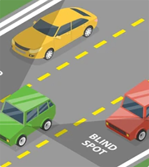
An onboard car safety system prevents car accidents by detecting the presence of an adjacent vehicle in the driver’s blind spot and warning the driver of a potential mishap. The driver can use this information to change lanes safely. In this article, we will discuss blind spot detection techniques.

Figure 1: Blind spot
Comparing the technologies
Turn assists monitor areas in the vehicle's proximity that are difficult or impossible for the driver to see and, if necessary, react appropriately. Most turn assists make use of either camera, Radar, or ultrasound.
Camera: Turn assists that use a camera use digital cameras to keep track of critical areas surrounding the vehicle. The driver can see the images through a monitor display in the cabin. These systems use algorithms to classify cyclists, pedestrians, and other objects. Such classification, however, needs significant computation. A major drawback of a camera system is that hostile weather and abnormal lighting conditions can impair its functioning.
Ultrasound: Turn assists that use ultrasound are well suited for determining distances from objects. The technology measures the return time of sound waves emitted by the system and picked up after reflection. However, ultrasound turn assists fail to determine directions or velocities and cannot accurately classify the detected objects. Ultrasonic sensors work efficiently at night but, like cameras, are susceptible to interference from rain, snow, and dirt.
Radar: The Radar turn assists can detect objects in the areas they monitor at the side of the vehicle or behind it. Like ultrasound systems, radar-based systems send signals reflected by objects within their range. In addition, they can take advantage of what is known as the Doppler Effect. Radar can, therefore, accurately measure both distance and velocity. Unlike camera-based and ultrasound-based systems, radar technology is immune to environmental factors like weather and lighting conditions. When augmented by algorithms, these systems permit the classification of the detected objects.
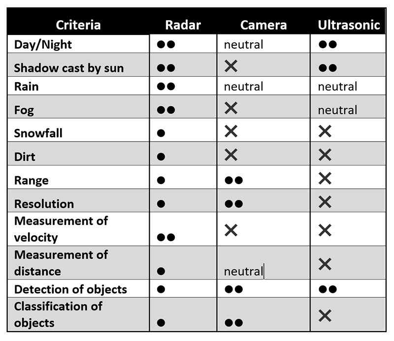
The three technologies thus differ in terms of performance. Camera-based systems are superior in terms of object classification and resolution. Higher resolutions create an excellent quality, crisp image. Radar-based systems offer significant advantages when measuring distance and velocity and are generally more resistant to environmental conditions than cameras and ultrasonic systems.

Table:1 Comparison
Development of Smart Vehicle Blind Spot Detection System based on radar and camera
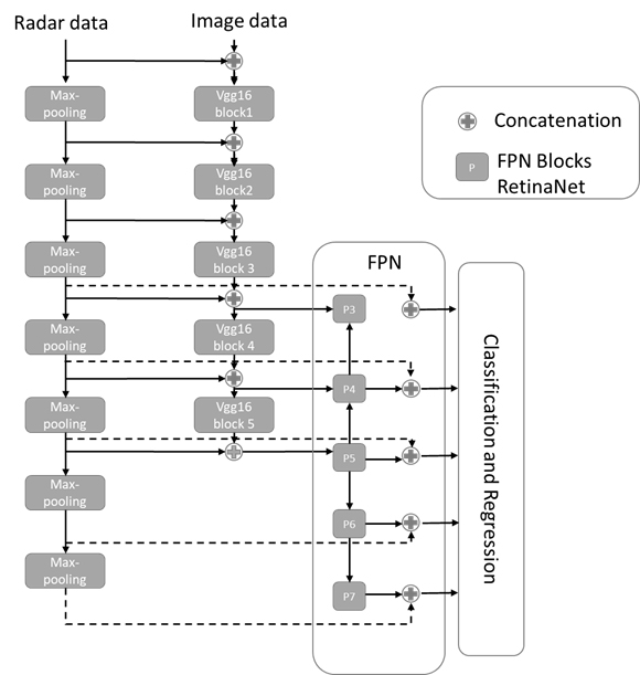
The neural network detects objects by combining Radar and camera data. Based on RetinaNet and using a VGG backbone, the network outputs a 2D regression of bounding box coordinates and a classification score. The term ‘backbone’ refers to a feature-extracting network synthesizing input data into a particular feature representation. VGGs are effective in image classification and object detection.
The network can be trained with focal loss, and the baseline method uses a VGG feature extractor during the first convolutional layers. The network is designed so that it learns by itself the optimal depth level for the fusion of Radar and camera data. Figure 2 shows the high-level structure of the network.

Figure 2: Structure of radar and camera
Preparing dataset and training
This section describes the dataset preprocessing and training
Radar and nuScenes dataset preprocessing
The radar sensor analyses data such as the azimuth angle and radar cross section (RCS) to output a 2D point cloud with associated characteristics. The data is transformed from the 2D ground plane to a perpendicular image plane and stored as pixel values in the augmented image. The input camera image with three channels (red, green, and blue) is combined with the radar channels to form the input for the neural network. The point clouds from three radars are concatenated and used as the projected radar input. The camera field of view (FOV) varies between datasets, with the calibration method used to map world coordinates to image coordinates. The difficulty of fusing data increases as the Radar needs to provide information about the height of the detections. The detections are assumed to be from the ground plane and extended vertically to account for objects' height. Traffic objects such as cars, trucks, motorcycles, bicycles, and pedestrians are detected and assumed to have a height extension of 3m to associate camera pixels with radar data. The radar data is mapped into the image plane with a pixel width of one.
Table 2 shows the original 23 object classes of the nuScenes dataset condensed into classes for detection evaluation. Ground-truth filters may or may not be applied to evaluate the nuScenes results.
Training
The raw data of nuScenes was split 60:20:20 to balance the amount of day, rain, and night scenes in the training, validation, and test set. The nuScenes images were used at an input size of 360 x 640 pixels. The mean Average Precision, can be calculated by weighting object classes based on their appearance in the datasets. The Imagenet dataset is used to pre-train the weights of the VGG feature extractor. The camera image channels were scaled during preprocessing, but the radar channels were not. Data augmentation is done to increase the relatively small amount of labelled data.

Table 2 : nuScene dataset objects per class
Farnell has partnered with many different suppliers catering to a wide range of industrial sensors and sensor connectors components products and solutions portfolios, such as radar camera and ultrasonic sensors. Element 14 is available for design execution, development, and projects.
Conclusion
A blind spot safety assistance system alerts the driver to any potential danger in their blind spots during driving. The technology reduces the risk of accidents and helps improve driver safety. The system uses camera, ultrasound, or RADAR sensors to detect obstacles or other vehicles in the driver’s blind spot. A warning signal instantly notifies the driver with a distinctive sound or light. The three technologies have their respective advantages. Camera-based systems are superior in terms of object classification and resolution. Among the three, Radar-based systems offer significant benefits when measuring distance and velocity and are generally more resistant to environmental conditions than cameras and ultrasonic systems.


