2D LiDAR using Time of Flight Sensors
The Time-of-Flight (ToF) concept is a method for non-contact distance measurements between an object and a sensor, based on the time elapsed between signal emission and its return after reflection from an object. This technology finds use in nearly every engineering discipline, including robotics, automotive applications, presence detection, medical technology, and optical navigation.
ToF based sensors use multiple signals, with light and sound being used the most. Light-centric ToF sensors have been predominantly substituted by the more accurate term LiDAR. Port automation, object protection systems, and traffic management systems are some LiDAR applications. Various available LiDAR devices are based on sensing mechanisms like 1D, 2D, and 3D LiDAR. This article will discuss the basic concept of ToF, its benefits, and an application example: 2D LiDAR using ToF Sensors.
ToF Basic Concept and Benefits:
ToF sensors compute the distance by measuring how long it takes a pulse of light to travel from the source to the observed target and then back to the detector. Figure 1 illustrates the procedure where a laser aims photons of light on a target. A few quanta of light, after they collide with the target, are reflected into the sensor. The following formula calculates the flight time:
Distance Value = Photon travel time/2 x the speed of light
To learn more about ToF technology, please click here
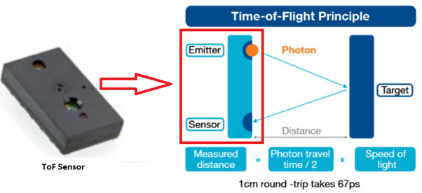
Figure 1: Time-of-Flight Principle
ToF sensors use time to calculate distances. This measurement is the time it takes for photons to journey between two points. Two techniques are employed to compute time: direct or indirect. ToF sensors based on both methods provide specific advantages in particular contexts. Both concurrently measure distance and intensity for each object pixel. Direct ToF sensors convey short light pulses that last a few nanoseconds and calculate the elapsed time it takes for the emitted light to return. Time is directly calculated via a precise time base. LiDAR is an example of a direct ToF sensor.
Direct ToF, regrettably, is laborious to design and unable to properly scale to high resolutions. Indirect ToF sensors communicate continuous, modulated light. The reflected light's phase difference is computed to calculate the object distance. A phase in the light wave is a particular point in time on the waveform cycle and is measured as an angle in degrees. A complete cycle comes to 360°.
A ToF sensor accurately detects objects instantly and remains unaltered by temperature, humidity, and air pressure. This makes it acceptable for indoor and outdoor use. It gives precise distance measurements. This technology is unaffected by optical path variations, ambient illumination, and independent of target object reflectance.
2D LIDAR using Time-of-Flight Sensor:
LiDAR stands for 'Light Detection and Ranging', a calculation technique where light is used to measure the distance to the closest object. To measure distance directly, they are aimed towards a reflector or particular target. Those sensors that process a single dimension (distance) through this technique are termed as 1D or one-dimensional sensors. Rotation of movement of the measuring beam on one level indicates the angle and distance, giving a two dimensions result. Sensors employed for such measurements are generally known as 2D LiDAR sensors or 2D laser scanners. They detect in ‘sequential order’ the measured values, typically at an equal interval of time between measurements.
LiDAR sensors, when pivoted, function in the third dimension. The pivoting action offers information concerning position and distance along the X-axis, Y-axis, and Z-axes. Identical information can be extracted about different space parameters if multiple sender and receiver systems positioned at different sensors scan horizontal angles during movement. This is termed as a multi-layer scanner.
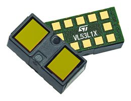
We will now discuss 2D LiDAR-based on nine VL53L1X long-distance ranging ToF sensors. It creates a simple environment depth map with a 180 ° Field of view (FoV). Such a system can be crafted using the VL53L1X ULD API (ultra-lite driver application programming interface), along with a C functions set controlling a single VL53L1X sensor or multiple VL53L1X sensors. This 2D LIDAR application is an excellent example of how to administer a large number of sensors.
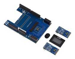
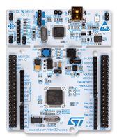
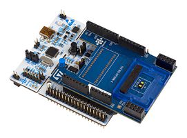
The full system is prepared using the P-NUCLEO-53L1A1 combined with the X-NUCLEO-53L1A1 expansion board and the STM32F401RE NUCLEO, as shown in figure 2. The nine sensors are attached to the VL53L1X breakout boards and share identical I2C interface, ground, and power. Each sensor reset pin connects to an allocated host GPIO pin.
Each of the nine sensors has a 20° FoV to cover the total 180° FoV of the LiDAR and the firmware is programmed to give 13 data points per sensor. So a complete 180° sweep would create 117 data points in total. The timing budget is around 12mS per sensor ‘zone’ and this would equate to a total sweep time of approximately 160mS. This would give a frame rate of a little more than 6 FPS. LiDAR System Operation

Figure 2: 2D LIDAR with multiple VL53L1X Sensors
2D LiDAR is used in several applications, including autonomous vehicles, agriculture, river survey, modeling pollution, archeology, and building construction.

